ESR is the equivalent series resistance of a capacitor. You can imagine it as a resistor connected
in series with an ideal capacitor. The value of this resistance is the ESR.
One of the most common faults of consumer electronics are just
defective electrolytic capacitors. Using a multimeter or capacitance meter can't reveal most of their faults.
Measuring ESR reliably finds defective electrolytic capacitors.
The deterioration of an etrolytic capacitor will first lead to its increasing ESR, later its capacity may also decline.
The high ESR of the capacitor may already cause a malfunction of the appliance, while the capacity is still good.
A great advantage of this ESR meter is that you do not need to desolder the capacitors,
because the measuring voltage is low and thus the surrounding components do not affect the measurement.
A standard capacity meter doesn't work with capacitors inside the board. It also can't identify faulty capacitors because
they often have a high ESR, while the capacity is still good.
For electronics repairman, an ESR meter is an absolute must. It's often used more frequently than a multimeter!
The measuring principle is simple: The capacitor is connected to an
alternating current of high frequency (typically 50-100 kHz) and the voltage drop across it is measured. A higher voltage drop means a higher ESR.
On the Internet there are many schematics of homemade ESR meters. Most of them, however, are very complex and utilize a microcontroller.
Other indicators have only one LED, which is not enough for the measurement of capacitors of many different sizes and values.
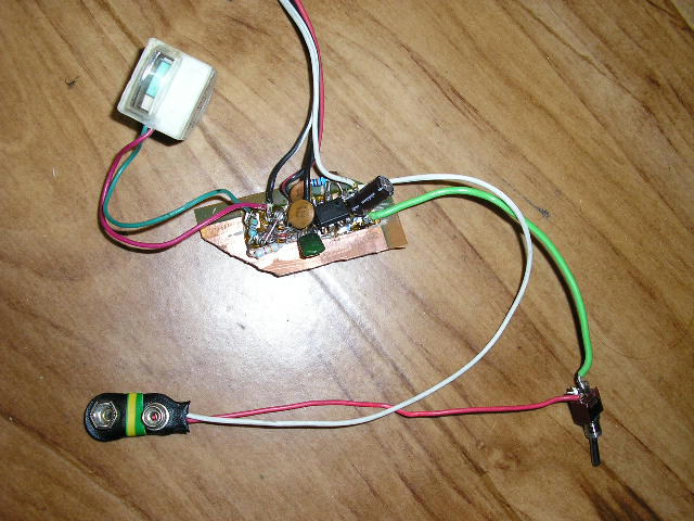
I chose a simple and effective solution. As a source of a high frequency current, about 50 kHz, I used a well known circuit 555. To measure the voltage drop
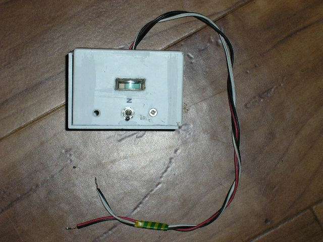
I used a small analog meter. You can use a small microamp or millivolt meter,
sufficient is a moving coil indicator, tuning indicator from an old radio or a sound level indicator (VU meter).
The rectification diode D1 has a low voltage drop, it may be a germanium diode (from
an old radio) or a Schottky diode. D2 protects analog meter against
excessive voltage while no capacitor is connecter. The values of resistors R1 and R2 must be
selected according to your analog meter. R2 is selected so that the analog meter is not over-range while no capacitor is connected, and R1 determines the
sensitivity. The test leads should be short (30cm / 1ft at most), because their resistance and inductance
may affect the measurement. Wires to the measured capacitor should be doubled (shown in the schematic diagram).
Larger electrolytes have a lower ESR, of course, so it is advisable to
make a scale according to typical ESR values of brand new capacitors. Sufficient is a logarithmic scale as 1uF, 10uF,
100uF, 1000uF. The meter is powered from a 9V battery. At open circuit condition the ESR meter draws about 6 mA and during measurement up to about 16 mA.