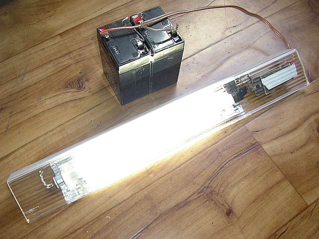
I created this Fluorescent Inverter 12V with goal - reaching the maximum
efficiency.
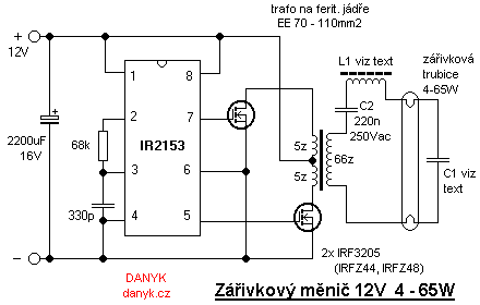
I constructed it as a push-pull inverter with MOSFETs. They are driven from circuit IR2153.
This ic is originally designed for excitation of the halfbridge, but it can also
be used in push-pull topology. The advantage of the circuit is that it has 2 outputs appropriate
for excitation mosfets and deadtime 1.2 us. It's a much better solution than the circuit with 555 or 556.
Working frequency is 35kHz (ideal frequency for RF excitation of fluorescent lamps). Circuit IR2153 has UVL, ie it wont run at a voltage less than 9V and
protects the battery from damage.
Inverter can power almost any lamp. Power (ie the current)
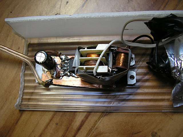
is set by L1. The C1 should also be selected according to the tube. For thin fluorescent lamps (T5 size, diameter 16mm, 4 - 21W) and
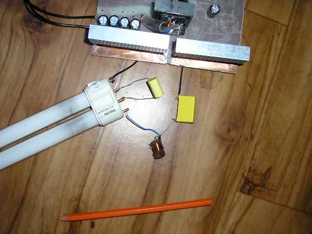
Small fluorescent DZ (U-shape or 2U, 5 - 18W, without integral starter - 4-pin) can be used capacitor and choke from almost any energy
saving lamps (CFL). Value of starter capacitor is about 2n2 to 3n3.
The tubes from compact fluorescent lamps can be directly connected to this inverter with their original HF ballast and starting capacitor.
Output voltage
and frequency corresponds to the ones from the compact fluorescent tube inverters (rectangular waveform at
approximately 160V 35kHz). For bigger fluorescent lamps (T8 26 mm or T12 38 mm and large DZ/PL) you must
use a coil with appropriate inductance and sufficiently rated, or combine 2 to 3 inductors from CFLs
in parallel. The current through fluorescent lamp
can be fine-tuned by changing the inductance of the coil (change of the air gap) or a small change in operating frequency.
Change is possible in the range of about 30 - 40 kHz and is conducted by changing the value of components in the oscillator (330p, 68k).
Start capacitor is chosen to be close to resonance with the choke. After switching
there is increased voltage around 500V produced by the series resonance, it strikes the lamp. C1 must be rated to 1000V.
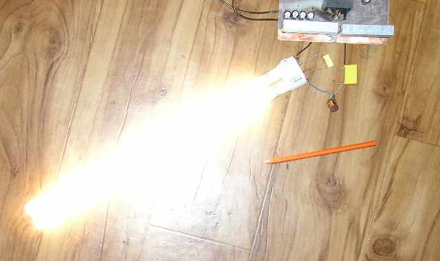
Due to the high efficiency,
the power into fluorescent lamps can be accurately estimated by the power drawn from the source of 12V. The converter can also drive
more lamps in parallel. Each then has its own capacitor and inductor.
The transformer has core without air gap. Used wire diameter must be rated
according to the desired output power. With small fluorescent lamps it is better to use transistors
IRFZ44 and a core with a smaller cross section.
Then he must increase the number of turns. Eg. if you use a core with cross section. 45mm2 instead recommended
core 90mm2, increase the number of turns of windings twice, ie 2x10 turns and 132 turns. The advantage of a smaller transformer
less load current.
Then a small lamp inverter is as effective as inverter for large lamp.
Transistors IRF3205
(55V 110A rON=0,008R max; td(ON)=14ns, tr=101ns, td(OFF)=50ns, tf=65ns, CGS=3250pF)
don't need heatsink for lower powers. Efficiency of this inverter is more than 90%.