Introduction:
The device is intended for wireless digital temperature measurement in range of -40 ... +70 °C with a resolution of 0.1 °C.
It can also record the highest and lowest measured value (maximum and minimum). It has LED display.
I created a 1-channel and then a 2-channel version.
Transfer method:
The signal is transmitted from the sensor to the display unit via RF communication modules on the 433 MHz band, on 433.92 MHz frequency.
This band is intended for data transmissions with a small amount of data and transmitter output power up to 10mW .
It can, however, use other band with no further adjustments, for example 868 MHz or 315 MHz (depending on what band is legal in your coutnry).
The transfer can use ready-made communication modules -
types that have 3 terminals: power supply , ground and input (transmitter) or output (receiver). Their use is very simple.
Logic pulses at the input of the transmitter simply appears at the output of the receiver, if it is within range and no interference with other devices occurs.
Data are transmitted by modulating the pulse length. In one frame 24 data bit are transferred - measured temperature value (11 bits), sensor ID (1 bit), parity bit and
check bits - bitwise inversion of temperature. A logic 1 is represented by 512us pulse length, 0 by 128us pulse, the gap between bits has always 256us, the gap between
frames is 1024us long. The difference between short and long pulses and between short and long gaps is always quadruple,
so that the transmission system is resistent to large variations of clock frequencies of transmitter and a receiver it is not necessary to use crystals.
The average data transfer rate is about 1800 bps.
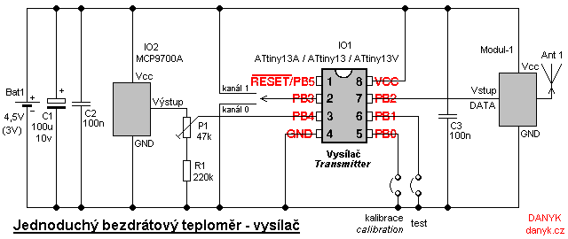
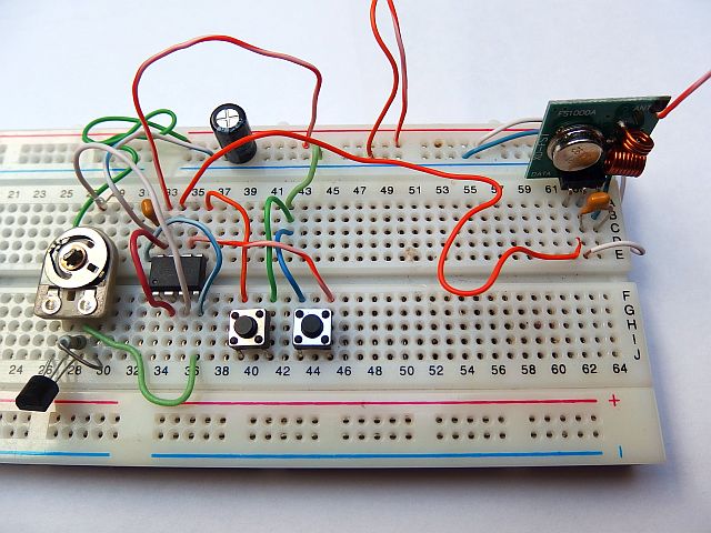
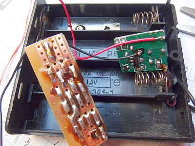
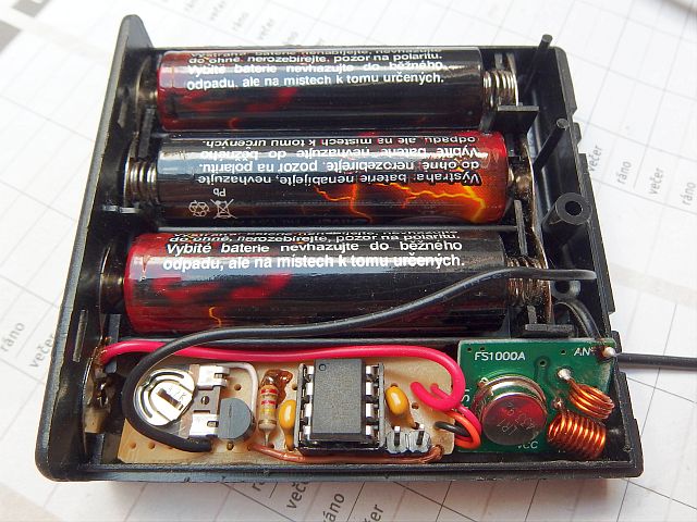
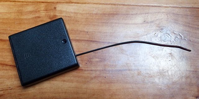
Transmitter:
Transmitter (wireless temperature sensor) is controlled by the IO1 - Atmel AVR microcontroller ATtiny13A (ATtiny13, ATtiny13V),
running at a frequency of 1.2 MHz from internal RC oscillator.
Data are transmitted using the radio signal. Temperature is sensed by is an integrated circuit IO2 - MCP9700A.
This provides the output voltage linearly dependent on the temperature with coefficient of 10mV / °C + 500mV.
Thanks added to added 500mV constant it allows measuring negative temperatures without negative output voltage. Current consumption of MCP9700A is only 5uA, which is
well suited for battery-powered device. Resolution of AD converter of IO1 circuit is
increased from 1024 to 1216 steps by oversampling, so that 0.1 °C measurement resolution is achieved. At each refresh, 38 AD conversions are done, they are added and
divided by 32. This generates the 11-bit result. For resampling, fewer samples would be sufficient, but more
samples leads to better stability and eliminates random errors. 1-bit ID of the transmitter is added, which allows
distinguish between two transmitters. From the resulting 12 bits a 13th parity bit is created.
Moreover, for more reliable transmission, 11-bit verification temperature inversion is sent
(zeros and ones swapped). Thus, the entire frame has 24 bits. This transmitted starting by the MSB of inverse temperature,
then the parity bit, then the channel ID and finally non-inverted temperature.
The frame is always sent 3 times during the transmission. The transmission repeats every 20s.
The sensor is calibrated using the trimmer P1. For easier calibration
you can increase the refresh rate from 1/20Hz to 1.5 Hz by connecting pin PB0 to ground. Then set P1 so that the receiver shows
correct value. By connecting the PB1 to ground you can activate transmission of the test signal - transmitter transmits all values gradually
from -40 to +70 °C. For normal operation, the inputs PB0 and PB1 unconnected.
Pin PB3 choses the channel ID. You can select channel 0 (input connected to the GND - the battery negative terminal) or channel 1
(connected to the positive terminal of the battery).
The same channel must be selected on the receiver (single channel). For use with two-channel receiver, set the one transmitter ID to 1 and the other one to 0.
Capacitor C2 should be placed as close as possible to IO1. Capacitor C3 should be placed as close as possible to the transmitter module Modul-1.
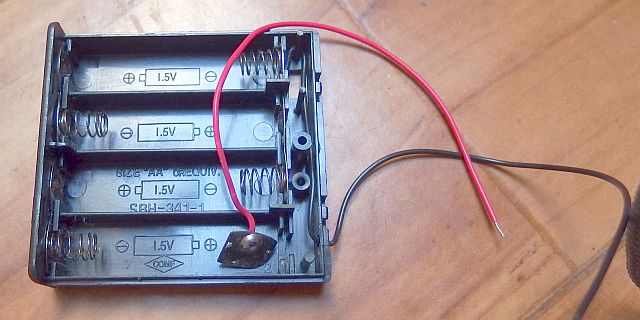
The transmitter is powered by 3V or 4.5V battery - two or three AA or AAA batteries, depending on the supply voltage
required by a transmitter module, or according to the required range. Average consumption is only about 25 - 30uA (FS1000 XD - FST, three 1.5 V cells) and operating time
with a 1000mAh battery (if not calculating self-discharge) is therefore about 4 years.
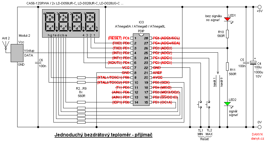
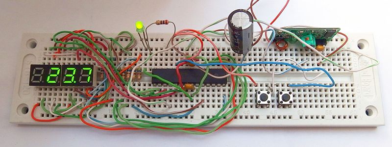
Single-channel Receiver:
The receiver (display unit) is controlled by IO3, ATmega8A (ATmega8, ATmega8L), clocked at 8 MHz from internal RC oscillator.
To display the temperature four digit LED display is used.
The display is controlled by the multiplex. Cathodes are connected to port B, the anodes to pins PD0, PD1, PD3, PD4 of port D.
Frequency of multiplexing is about 100Hz. Resistors R2... R9 determine the current into display and thus the brightness.
You can use a four-digit display as CA56-12SRWA or two two-digit ones as LD-D056UR-C, LD-D036UR-C, LD-D036UPG-C, LD-D028UR-C or LD-D028UG-C.
You could also use the three-digit LED display and a rectangular LED as segment g of digit at left side (minus symbol), because there really is nothing else being displayed.
The right digit can be omitted, when 1 °C resolution is enough (and then the resistor from PB7 to segment h can also be omitted, because the dot is not needed).
The RF receiving module Modul-2 is used to receive the signal from sensor. The output is evaluated by a microprocessor IO3.
It evaluates and processes the received signal, and if it accepts the code in the correct shape - the length of 24 bits, the desired channel (transmitter ID),
parity bit is OK and inverse value too,
evaluates the frame as correct and updates the display. The receiver also monitors and records the maximum and minimum measured values.
These can be displayed by pressing the MIN or MAX buttons. Pressing both buttons at the same time resets the maximum and minimum.
Pin PC3 serves as an indicator of signal reception. When in the last 60s the signal was received, it is in log 1 state and LED2 is lit.
Otherwise, it turns into log 0 and LED1 is lit.
The thermometer is powered from 5V supply. Current consumption is about 20-40 mA (most of which is consumption LED display).
Put capacitor C5 as close as possible to IO3 and capacitor C6 close to receiver module Modul-2.
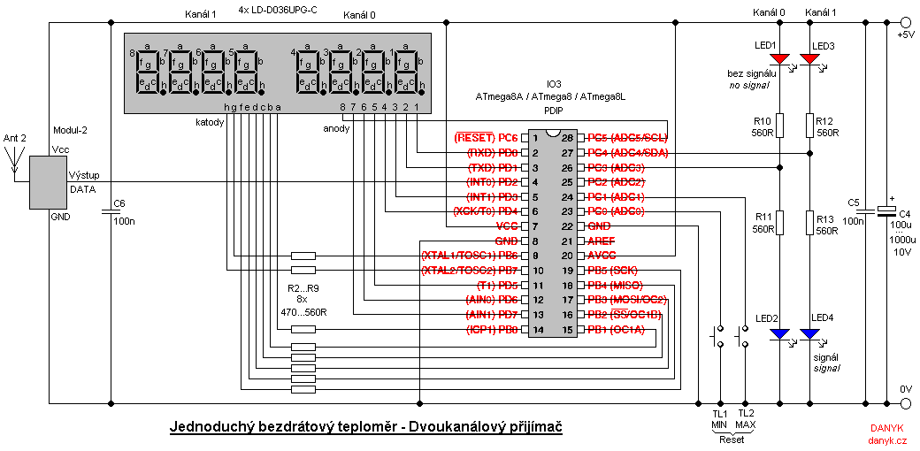
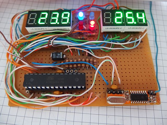
Two-channel receiver:
Later, I created 2-channel version of receiver (see the diagram in Figure 3).
This allows you to simultaneously receive signals from two different transmitters (one transmitter is set to channel 0 and one to channel 1).
It has the two four-digit displays, assembled from four two-digit LD-D036UPG-C. Each channel has its own signal indicator.
Minimum and maximum buttons are common for both channels. Otherwise everything is similar to the single-channel receiver.
Range:
Receiver software fixes various transmission errors and interferences, especially ringing, pulses and gaps of incorrect length, etc.
Range depends therefore mainly on the transmitter and receiver modules and also on surrounding obstacles and sources of interference.
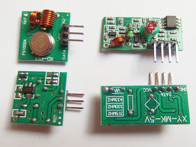
For the first tests I used the communication modules
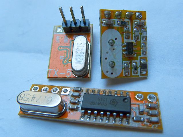
FS1000A XD-FST (transmitter) and XY-MK-5V (receiver), here are the reverse engineered schematics , and then I tried also modules
BX-TM05-433 (transmitter) and BX-RM12-433 (receiver). Both pairs are using ASK modulation. The first pair had, however, ragne only about 2-8 meters in free air.
Receiver (XY-MK-5V) turned out to be a regenerative or superregenerative type. It is a primitive circiut with two transistors and OpAmp,
it has a low sensitivity and selectivity.
Even a relatively powerful transmitter FS1000A XD-FST didn't compensate the low sensitivity.
The receiver needs 5V supply and even small deviations of voltage make the range even worse.
Just by looking at the receiver you can't expect much of it, as instead of a crystal you can see a tuning coil (!).
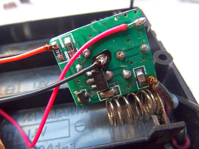
FS1000A XD-FST transmitter has 10mW max power, supply voltage range is 3 - 12V. The transmitter is controlled by the SAW resonator
433.92 MHz and should therefore be relatively stable (tolerance of resonator according to the datasheet is +/- 75kHz).
It contains only two transistors, no integrated circuits.
Then I tried a pair of BX-TM05-433 and BX-RM12-433 and it was quite another story. Range of 15m through floor and two or three walls is not a problem.
The receiver is a superheterodyne (superhet) with quality SYN470R circuit, controlled by crystal (6.7458 MHz), supply voltage is 3 - 5.5V.
Transmitter with 6-pin SMD integrated circuit labeled F113 is also controlled by a crystal (13.56 MHz) and apparently works as a PLL.
The accuracy of the frequency of the crystal is probably a little better than SAW resonator. Power is
1.8 to 3.6 V. The best possible range I gained by combining the powerful transmitter FS1000A XD-FST from the first pair and the receiver BX-TM05-433 from the other pair.
FS1000A XD-FST allows better range than the BX - TM05 -433 (both tested at 3V), and can also work with higher voltage, so the range can be further
increased.
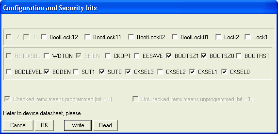
The wireless thermometer program for free download:
Transmitter source code in assembler (ASM)
1-channel receiver source code in assembler (ASM)
2-channel receiver source code in assembler (ASM)
Compiled Transmitter HEX file (358 Bytes)
Compiled 1-channel receiver HEX file (810 Bytes)
Compiled 2-channel receiver HEX file (1204 Bytes)
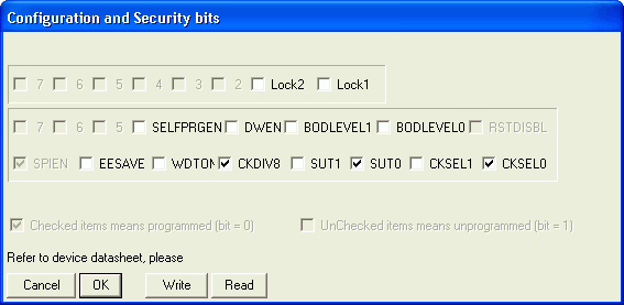
How to write the program into the AVR is described here.