Intro:
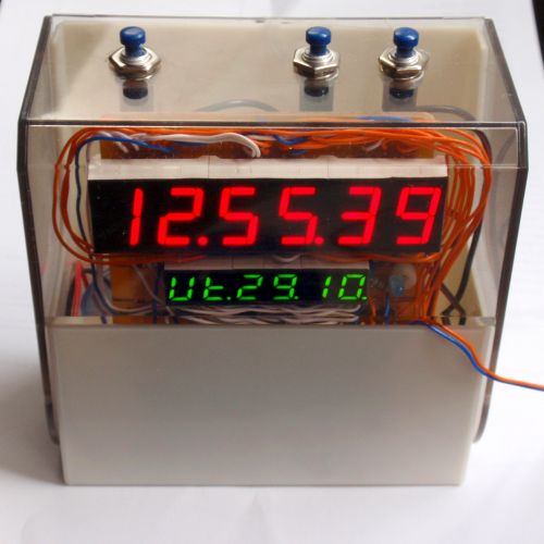
This clock was created to display the time, including seconds, date and the day of the week.
It also has a stopwatch, alarm clock and countdown (timer) and an automatic transition between winter and summer time (daylight saving time).
The date works correctly even for leap years. The clock is equipped with a backup battery.
The running speed can be digitally adjusted from -120ppm to + 120ppm.
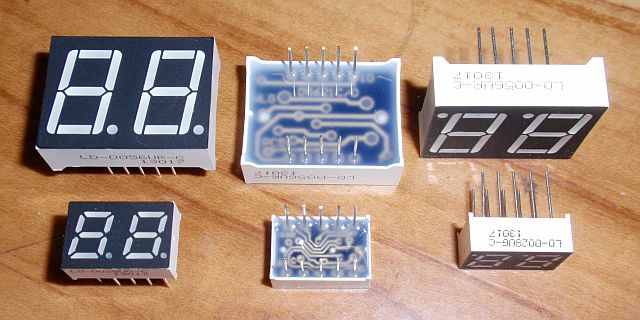
The displays are 2 six-digit 7-segment LED displays with adjustable brightness.
Schematic:
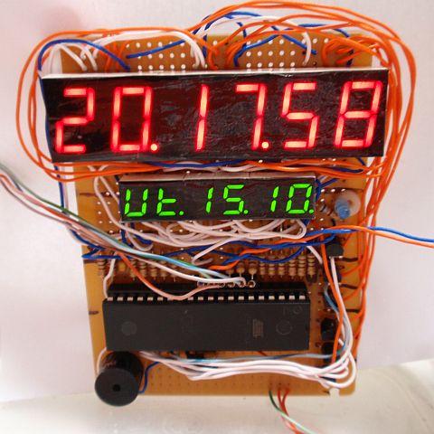
The DISP1 display consists of three LD-D056UR-C, DISP2 of three LD-D028UG-C, both are high-brightness types with a common anode, controlled in multiplex.
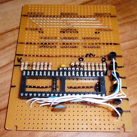
The anodes are switched by current-amplifying transistors T1 to T6 (emitter followers). The cathodes are controlled directly
from microcontroller IO1 via series resistors R1 ... R16. The multiplex frequency is approximately 100Hz.
The accuracy of the clock is ensured by the low-frequency crystal X1 (32 768 Hz).
The small speaker Rep1 serves both the alarm clock and the timer. Simultaneously with the sound of the alarm and timer, LED1 also lights up (this can be omitted or
you can use this output, for example, to switch a relay). The clock is controlled by the Minutes (TL1), Hours (TL2) and Mode (TL3) buttons.
The circuit is powered by a 5V +/- 10% power supply (eg with a simple voltage regulator with 7805). The current consumption depends mainly on the
selected brightness of the display and the number of currently lit segments.
At the highest brightness, the consumption shouldn't be more than 100mA. The clock has a backup battery. When operating from it,
the display does not light up and the buttons are also disabled, except stopping the alarm and timer sound.
For the backup you can use 3V, 3.6V, 3.7V or 4.5V battery. It can be, for example, one 3V lithium button cell,
two to three 1.5V AA or AAA cells, three 1.2V NiMH / NiCd cells
or one 3.7V Li-ion / Li-pol cell. The consumption during operation from a 3V battery is only about 10uA. Operating time from a 3V CR2032 cell with usual 220mAh capacity
is 2.5 - 3 years. When the alarm rings while powered from the battery, the battery consumption increases.
The presence of the 5V supply voltage is sensed by pin 36 (PA4), log 0 switches the clock to power saving battery operation.
This input can also be used to turn off the display or briefly turn it on during battery operation.
Both power supplies are connected via Schottky diodes D1 and D2 with low voltage drop, eg SB160, SR160, 1N5817, 1N5818 or 1N5819.
D1 prevents current from flowing from the battery back into the AC power supply
and protects the clock circuit from polarity reversal. D2 prevents the battery from being charged unintentionally during mains operation.
Program:
I give the program of this multifunctional clock for download in a HEX file directly for uploading
to the microcontroller and also as source code in Assembly (ASM) for possible modifications.
Warning: The program is quite complex and confusing.
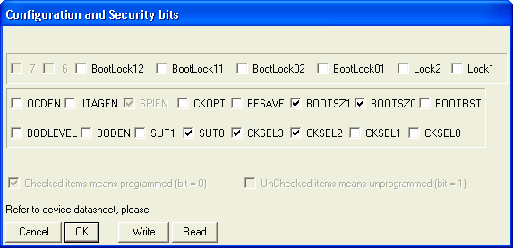
The picture below shows the Atmel AVR configuration bit settings (Low Fuse: E3, High Fuse: D9).
The MCU runs at 4MHz from the internal RC oscillator, Timer/Counter2 runs asynchronously from the 32 768 Hz crystal.
When idle during mains supply, IO1 switches to Idle sleep mode
and when running on battery power it switches to Power Save mode and therefore has very low power consumption.
Using the clock functions:
The TL1 and TL2 buttons are used to control the current function.
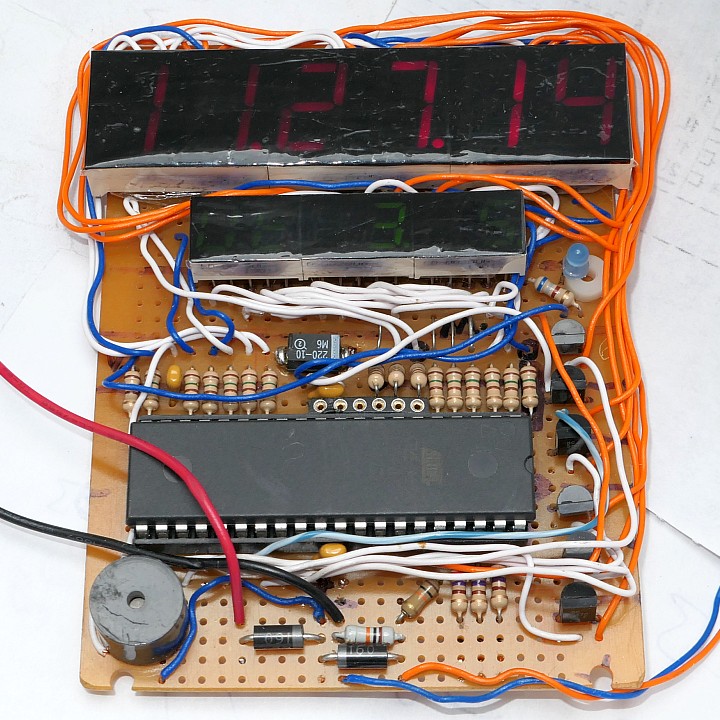
The main display DISP1 always shows the time in "Hours.Minutes.Seconds" format. Display DISP2 shows other functions,
switched by TL3 button (mode):
• 1. Date
"Day_of_the_week.Day.Month" format. Buttons TL1 and TL2 adjust the brightness of the display in 6 levels: 1/1, 1/2, 1/4, 1/8, 1/16 and 1/32.
• 2. Audio signal duration + alarm mode
The TL1 button is used to turn on / off the alarm and select its mode:
"A_" = off alarm, "A1" = one-time alarm (then automatically set to off),
"A5" = alarm only on weekdays (Mon-Fri yes, Sat-Sun no), "A7" = alarm every day.
The default setting is alarm off.
The TL2 button selects the duration of the sound signal (as well as the LED1).
You can select an infinite duration (does not turn off by itself), indicated by "n" on the display, or a duration from 1s up to 96h.
Such a long time can be set so that the clock can also be used to control a relay. The signal duration setting also affects the timer signal.
• 3. Alarm
Setting of alarm, "HH.MM.AL" format.
Button TL1 sets the alarm minute, TL2 sets the alarm hour.
• 4. Stopwatch
The stopwatch allows you to measure time with 0.1s accuracy. The maximum time is 9.59.59.9 (almost 10 hours). The format is
Hour.Minutes.Seconds.Tenth_of_a_second. The TL1 button is used to start and stop the
stopwatch. The TL2 button is used to reset (running stopwatch is stopped by the first press and reset by the next one).
• 5. Timer (countdown)
Timer (countdown mode) - countdown from a selected time to zero. Then an acoustic signal is triggered and LED1 lights up.
Press TL3 to turn off the signal. (Acoustic signal duration can be limited as with the alarm clock.)
The display is in "Hours.Minutes.Seconds" format. The last dot lights up when the countdown is stopped.
The TL2 button is used to go througt digits while setting the initial value. TL1 is used for setting.
The digit currently being set flashes at 5Hz. The maximum set value is 99.59.59 (almost 100 hours).
After setting all digits, press TL2 to return to countdown mode.
Here, the TL1 button is used to start and stop the countdown.
Setting the clock:
Press and hold TL3 to enter the settings. You then set the clock in five steps, toggled by pressing TL3 briefly.
• I. Automatic summer time, language
TL1 sets the language for the day of the week ("day CE" - Czech, "day En" - English), TL2 enables the automatic summer/winter time ("Auto 1" - on, "Auto 0" - off).
• II. Speed correction
The 2nd display shows "Cor.PPM", the 1st display shows the acutal setting. Use TL1 to speed the clock up, TL2 to slow it down. You can set the clock speed
adjustment from -120 to +120 ppm (parts per million).
• III. Day of the week and year
TL1 sets the year, TL2 sets the day of the week.
• IV. Date
TL1 sets the month, TL2 sets the day.
• V. Time
TL1 setst the minutes, TL2 sets the hours. (The seconds are reset to 00 when the minutes are being set.)
The program for download (new):
source code in Assembly (ASM)
compiled in HEX file (4 828 Bytes)
The program for download (old version from 2013):
source code in Assembly (ASM)
compiled in HEX file (3 896 Bytes)
How to write the program into the AVR is described here.