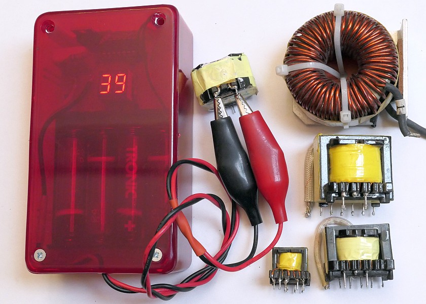
This is a simple tester of switching transformers and inductors. It can detect a short circuit in the winding.
It tests based on the loss in the inductor or transformer. Even a small number of short turns (and even a single shorted turns)
will cause a significant increase in losses (a significant reduction in the Q factor).
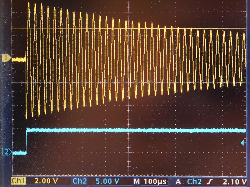
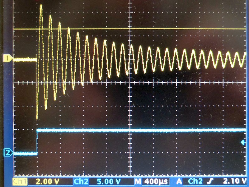
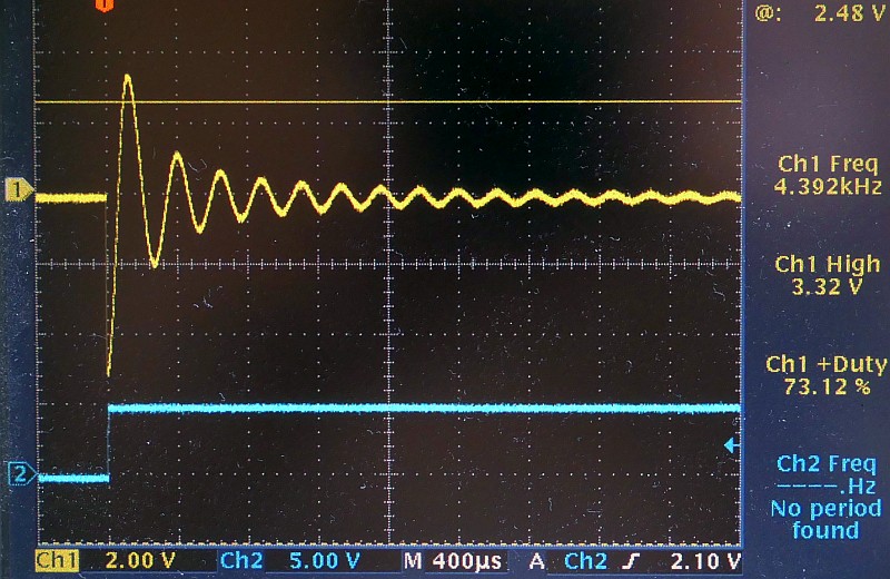
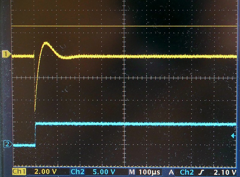
A charged capacitor is connected to the inductance during the test and damped oscillations occur. The number of oscillations that occur is counted,
until their amplitude falls below the threshold value (here approx. 1/2 of the supply voltage - the threshold of the logic inputs of the used microcontroller).
The number of oscillations is displayed. This number will be significantly lower for damaged (shorted) windings.
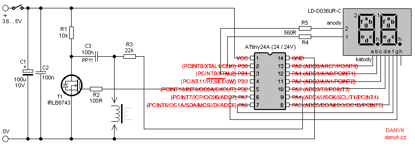
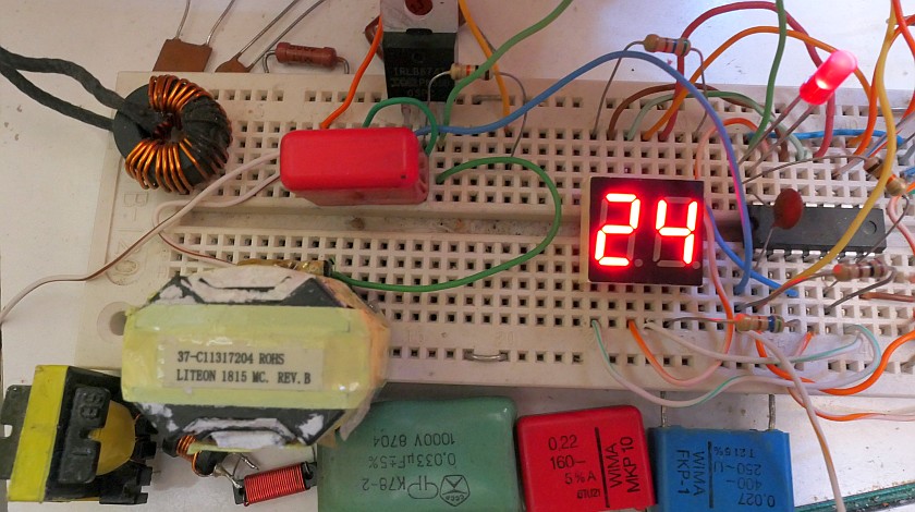
It is displayed using a two-digit LED display with a common anode. It is controlled by Atmel AVR ATTiny24A microprocessor (ATTiny24, ATTiny24V),
the program for downloading and setting bits are below.
The cathodes of the two-digit LED display (a-g) are connected to the PA port (except for the PA4 pin).
The anodes are connected to bits 0 and 1 of the PB port. The dot cathode (h) is unused, the dot does not need to be displayed.
Using a high-brightness display allows you to omit the usual
current amplifying transistors. The display is multiplexed. It uses multiplex by segments in 7 steps, not the usual multiplex by digits.
This allows you to use only 2 series resistors instead of seven.
The microprocessor is clocked by an internal RC oscillator operating at 8MHz.
The multiplex frequency is about 100 Hz.
Resistors R4 and R5 determine the current of the display and thus its brightness.
The consumption at 5 V is approx. 5 mA, if nothing is connected to the test terminals, and approx. 8 - 15 mA during testing.
The circuit can be powered eg from a switched 5V power supply, power bank, linear power supply with 7805 circuit, Li-Ion / Li-Pol cells 3.6 or 3.7 V, 3 alkaline cells 1.5 V or
3 - 4 rechargeable NiMH or NiCd 1.2 V cells. I used 4 NiMH AA cells.
Insert a suitable fuse in series with the power supply or battery! Place ceramic capacitor C2 as close as possible to terminals 1 and 14 of the
microcontroller. Capacitor C3 is critical and must have a very low dissipation factor (tan δ), I recommend using a good quality polypropylene film capacitor.
Please note that with a ceramic capacitor the circuit will not work and with a polyester one it will only work very poorly. Transistor T1 is an N-channel logic MOSFET.
At the applied supply voltage (minus a certain voltage drop of the microprocessor output) on its gate
it must already have a very low ON state resistance (in the order of ones of milliohms). For this reason, 4.8 - 5V supply voltage is better.
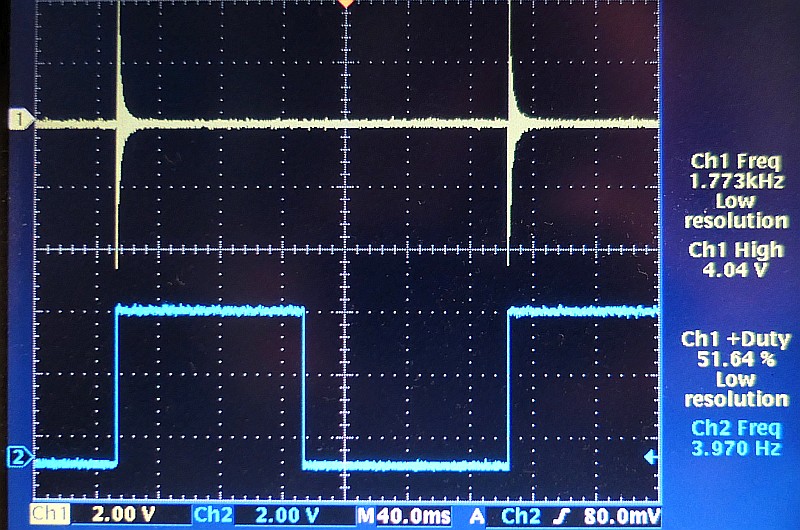
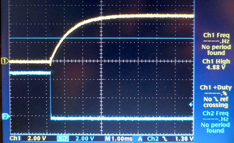
When the transistor is off (approx. 130 ms), the capacitor
C3 is charged through resistor R1 and the inductance tested. When the transistor turns on (approx. 120 ms),
damped oscillations occur. They go to the PA4 input of the microprocessor through the resistor
R3 and they are counted. Everything is repeated every 250ms and the display is therefore refreshed at a frequency of about 4 Hz.
You might be also interested in the improved version - Transformer, inductor and capacitor in-circuit ring tester,
which can test the transformer or inductor without desoldering it from the circuitboard.
The AVR program for download:
source code in Assembly (ASM)
compiled HEX file (364 Bytes)
Low fuse = E2, High fuse = DD, Extended fuse = FF, Lock fuse = FF