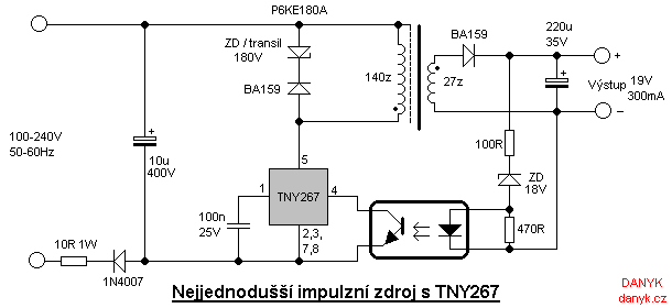
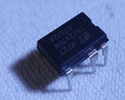
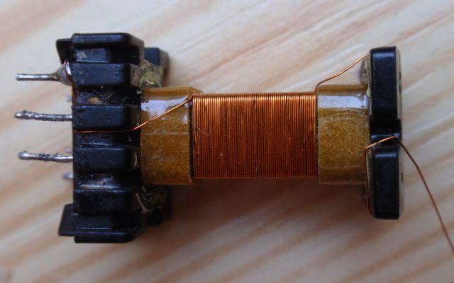
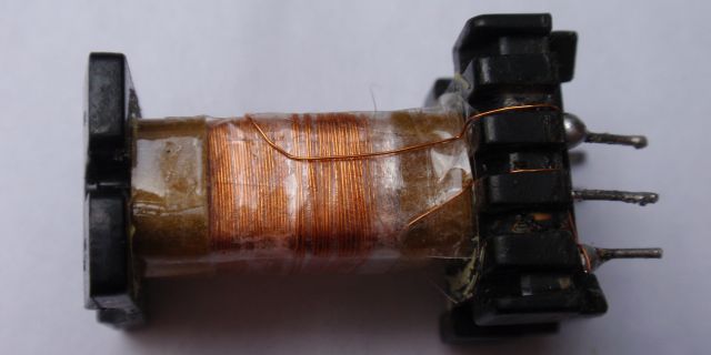
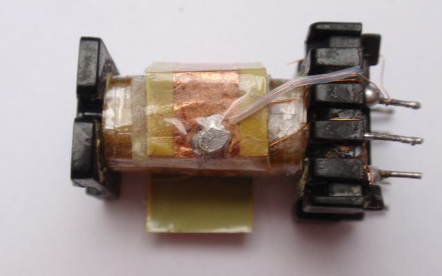
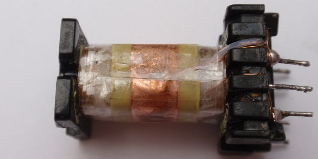
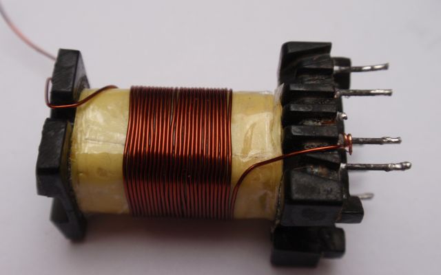
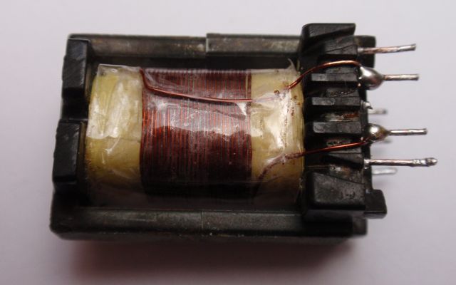
I tried to build as simple as possible switching power supply. It uses an integrated circuit TNY267P of a series of circuits TinySwitch-II: TNY263, TNY264, TNY265, TNY266, TNY267 a TNY268. This component integrates both the control circuit and the switching element (MOSFET), current and thermal fuse and self-power system. This is everything needed for a small flyback supply. It doesn't even need an auxiliary winding. All this is fitted into DIP8 package (same as the 555)! Its maximum voltage is 700V, the working frequency is 132kHz. Schematic diagram you can see below. Due to the low power, I used halfwave rectifier. Voltage peaks are limited using transil (zener diodes) 180V. This can be replaced with the usual parallel combination of resistance and capacitor. Feedback is provided with optocouplers, the threshold is chosen simply using zener diode (ZD). ZD determines the output voltage. It is about 1V greater than the nominal voltage of ZD, because the voltage drop of the LED optocoupler is involved. For 19V output voltage ZD 18V is applied. Of course i don't force you to build build 19V supply - output voltage can be adjusted by changing two things: - Secondary winding is about 1.4 z / V. - ZD is about 1V less than the required voltage. For low voltage (about 5V or less) replace fast diode on output with Schottky diode. Maximum power of this supply in an enclosed adapter and 230V power is 13W. Transformer is a small ferrite EE. Central column has a cross-section of 4.5 x 4.5 mm, air gap 0.4 mm. Primary has 140 turns of wire diameter 0.15 mm. Secondary has (for 19V output) 27 turns of wire 0.4 mm. Due to the low power the secondary is not divided to two parts. First, I wound the entire primary. The layers are interlaced primary. Between primary and secondary i used shielding - copper tape and connected it to the cold end of primary (of course it must not create a short turn!). Then I wound strong isolation - 12 layers of duct tape. Then I wound secondary. In case of problems with interference add a noise suppression circuit and / or use a capacitor approximately 1n / Y1 between primary and secondary side. Detailed parameters can be found in the datasheet of TNY263 - TNY268. The higher part the number, the higher the potential power. Note also the newer series of TinySwitch-III: TNY274 - TNY280. In this series you can find IC's allowing even more power. They can also fit into schematic below, only the pinout is different.