This is a simple charger for Lithium-ion (Li-Ion) and lithium polymer (Li-Pol) cells with well-known integrated circuit LM317.
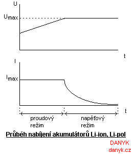
Charging characteristic is shown in the graph below. Charging takes place first in the current mode - Rising voltage,
the current is constant. After reaching the target voltage (Umax), the charger goes into voltage mode when the voltage is
constant and the current asymptotically approaches zero. At the moment the current is small, the cell is charged.
Target voltage of Li-ion and Li-Pol accumulator is usually 4.2 V (for some types 4.1 V) Target voltage is not the same as the nominal voltage.
It is generally 3.7 V (sometimes 3.6). The cell does not need to be charged the full 4.2 V, because it decreases its lifetime. If you reduce
the target voltage to 4.1 V, capacity drops by 10% but lifetime (nubber of cycles) will increase almost twice. When using the cells, they
should never discharge below 3.4 to 3.3 V. Cells Li-ion and Li-pol do not like storing in a charged or discharged state, they should
be stored partially charged.
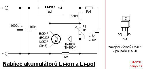
Charger schematic is shown below. Circuit LM317 serves as the voltage stabilizer. Li-Ion and Li-Pol is quite demanding on the accuracy of
charging voltage. If you want to charge to full voltage (usually 4.2 V), it is necessary to adjust this voltage to with +/- 1% accuracy.
Cells are very sensitive to overcharging.
If you charge at 90% capacity (4.1 V), is sufficient a little less accuracy (around 3%). LM317 circuit provides a relatively accurate voltage
stabilization. The target voltage is set by
trimmer P1. We set it without connecting the cell, because the target voltage corresponds to the output voltage with no load.
Stabilization of current is not as critical as the stabilizing voltage, so it is sufficient to stabilise it by a shunt resistor
and NPN transistor. If the drop of shunt Rx reaches approximately 0.95 V (the total voltage drop of the NPN transistor's B-E and diode 1N4007)
transistor starts to open. This reduces the voltage on the pin adj and so it stabilizes the current. Current is depending
on value of Rx. Select it according to the type of charged cell. For charging current 200 mA, I used the value of 4R7.
The value of Rx is calculated: Rx = 0.95 / Imax.
It is good to connect appropriately dimensioned fuse in series with the cell for safety reasons.
Supply voltage should be in the range of about 9 - 24V. Too high voltage increases the power loss of circuit LM317,
too low would not allow the proper operation (it is necessary to count the voltage drop on shunt and minimal voltage drop for
the integrated circuit). LM317 circuit should be placed on a sufficiently large heat sink.
The charger is resistant to short-circuit at the output. LM317 in worst case (short circuit) dissipates a power loss:
P = U in x I max. The maximum allowable loss of LM317 in TO220 version is 20W.