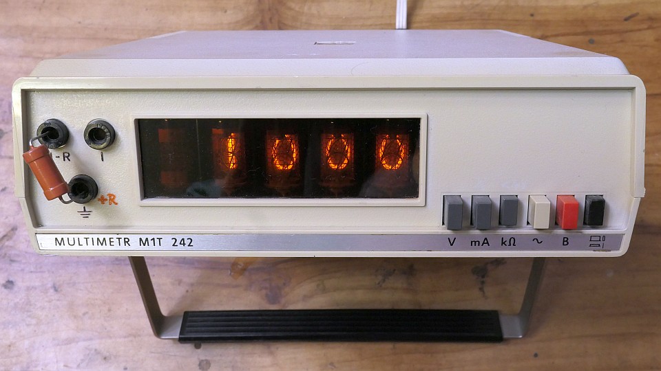
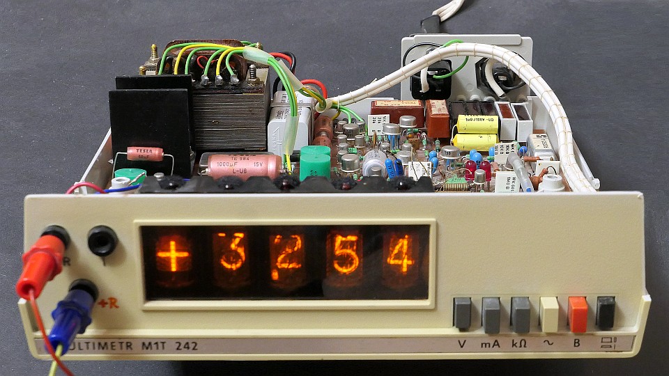
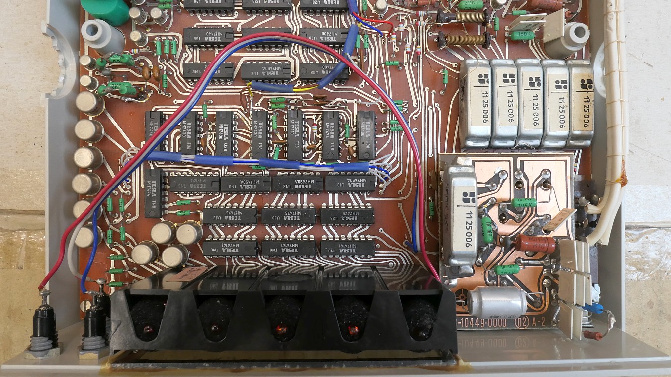
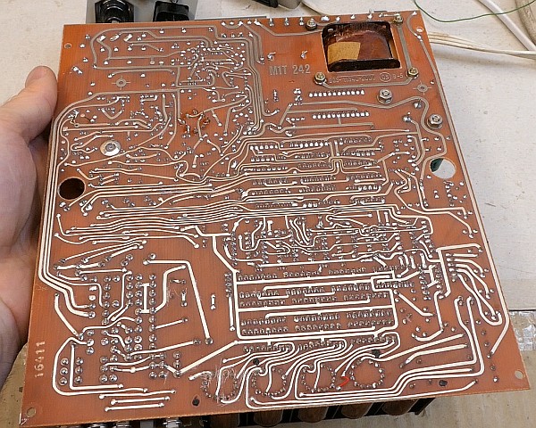
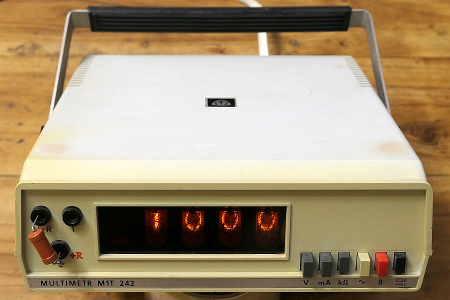
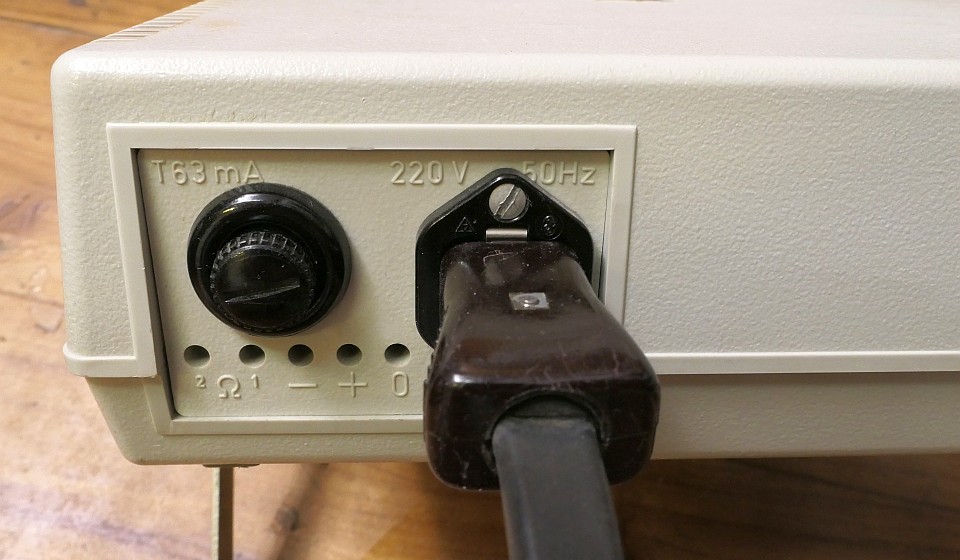
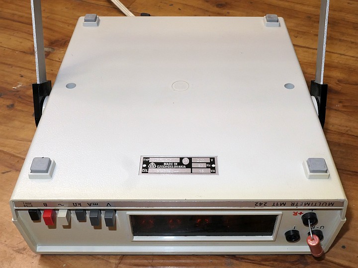
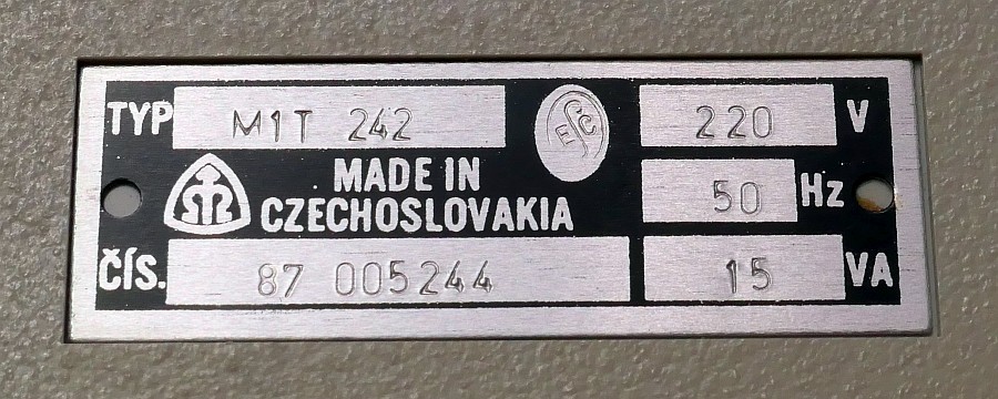
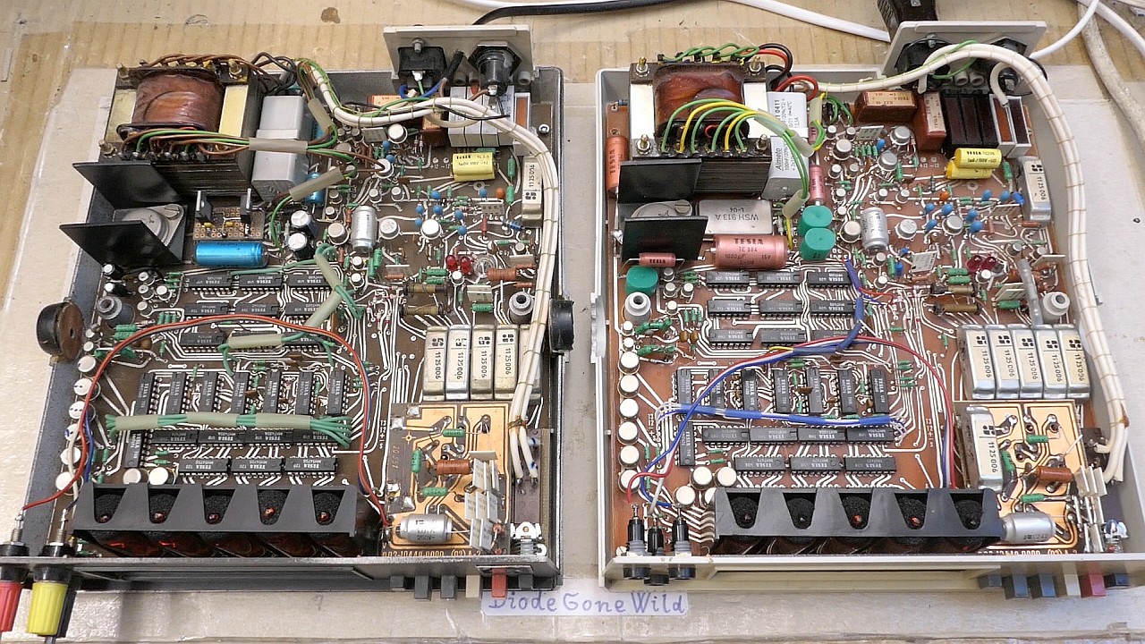
Digital bench multimeter M1T 242 was produced by Metra Blansko in the 1980s using mainly Czechoslovak Tesla components. Nixie tubes are used for the display, which in some versions were probably Tesla ZM1080T and ZM1081, but in my two devices, East German RFT Z574M and Z571M are installed. There is always one symbol nixie showing + and - polarity or the AC voltage ~ symbol, followed by four numeric nixies with a decimal point displayed on the left. This multimeter measures DC and AC voltage, DC and AC current, and resistance. Each is measured in 4 automatically selected ranges. Voltages are measured in 0.3V, 3V, 30V and 300V ranges. For AC voltages, the input resistance is 1MΩ. Oddly, for DC voltages, the input resistance is above 100MΩ for the 0.3V and 3V ranges, but 10MΩ for the 30V and 300V ranges. Currents are measured in 0.3mA, 3mA, 30mA and 300mA ranges (the voltage drop at full current is always 300mV). Resistances are measured in 3kΩ, 30kΩ, 300kΩ and 3000kΩ ranges. It switches to a higher range when reaching 110% of the range value. For example, when 3.3V is exceeded, it switches up to the 30V range, and when the voltage drops below 3V, it switches down to the 3V range. The analog-to-digital (AD) converter has 3300 counts. On the left side of the front panel there are three sockets - the common GND terminal, a socket for measuring voltage + resistance and a socket for measuring current. On the right side of the front panel there are buttons for selecting voltage, current and resistance measurements, a switch for selecting DC or AC, a switch blocking the automatic range selection and a power switch. On the back of the device you will find a connector for connecting the mains cable, a T63mA fuse and 5 holes ti set multi-turn calibration trimpots. The device is powered by a 220V ac 50Hz mains, the consumption is 15VA. There's also an M1T-242A version, very similar, but it uses VQE24 green LED displays instead of nixies.