Multiphase synchronous rectified step-down or so called buck converter is most commonly used in PC motherboards.
It is used to reduce the supply voltage of the ATX (usually 12V, 5V sometimes) to a lower voltage (usually only about 1-2V)
to power the CPU processor core. Processors need a very small voltage and high-current, about tens of Amperes.
The inverter operates as a step-down, which divides the power between several separate power circuits,
working with phase shift. In article about the inverters it is the topology of L.
Usually the diodes are replaced by MOSFETs, which serves as a synchronous rectifier, thereby reducing losses (
ON state voltage drop is much smaller than the drop in Schottky diodes). The phase shift of multiphase converters
enables easier filtration.
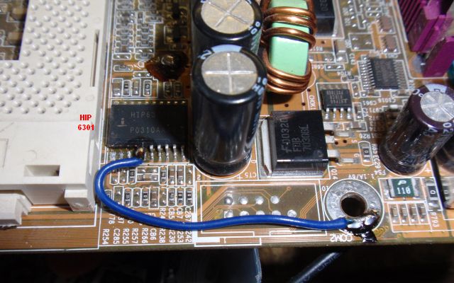
The inverter is usually controlled by a circuit HIP6301 that can perform two, three or four phases with phase shift
180, 120 or 90 degree. It provides a pulse width modulation PWM, power balancing between channels and
overload protection. Working phase frequency may be 50 kHz to 1.5 MHz in this controll IC. Frequency of output
ripple is multiplied by the number of channels. It is powered from 5V. Sometimes we meet also with its equivalent HIP6302, which
only works with two phases. For the driving of the halfbridges the circuits HIP6601 or HIP6603 are usually used (or their double
analogies HIP6602 and HIP6604). These circuits allow the drive of the upper and lower MOSFET and an operating voltage of 10-15V.
Includes protection against the opening of both MOSFETs at the same time and hard switching. The principle of their operation is a bit like
circuit IR2101-2104 or the output of the IR2153, but the input voltage is only up to 15V and it has hard switching and cross-conduction protection.
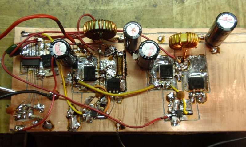
I tried to build the two-phase buck, and I also tried to utilize three-phase inverter directly on the motherboard.
Both attempts werw successful :).
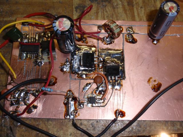
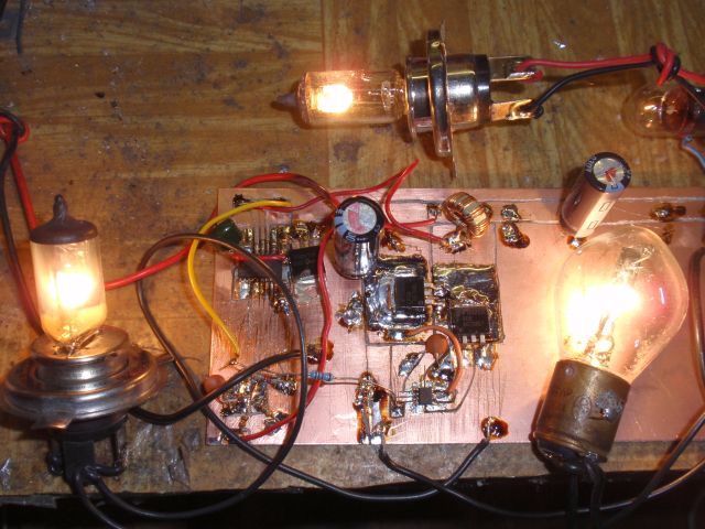
On an experimental board, I successfully compiled single phase (the other phase not connected) and then a two-phase inverter.
Each phase can supply easily approx 10A, thus 20A together permanently. I used MOSFETs FDB6670AL with on resistance 5mR.
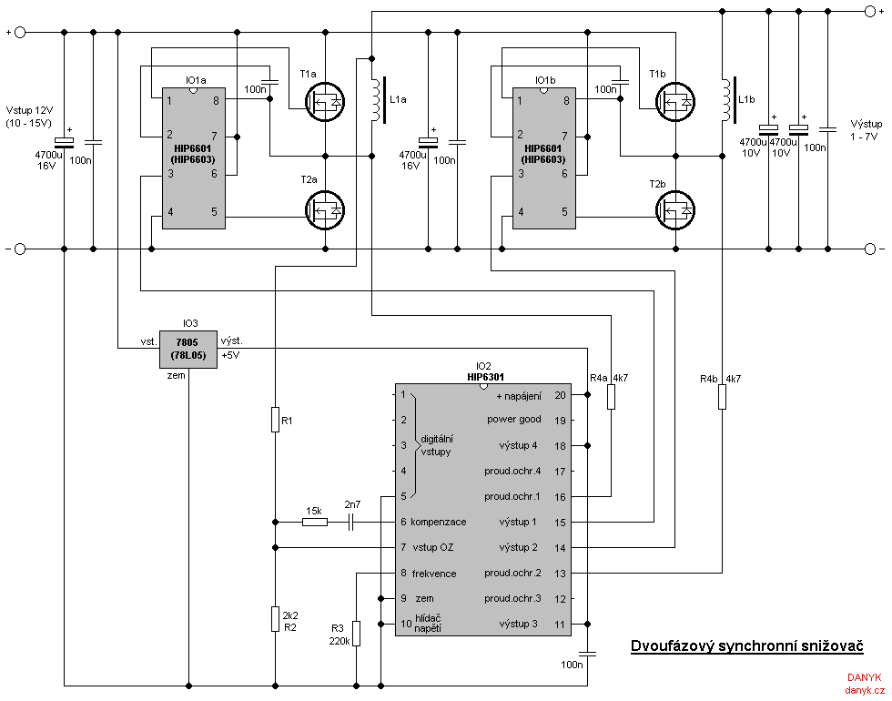
Most of the parts I got from defective motherboards. The circuit diagram below shows an inverter with two phases.
Integrated circuit HIP630x has digitally switchable reference voltage using a 5-digital inputs (a total of 31 different values) from 1.100 V to 1.850 V.
It is designed to operate without a resistive divider, so the output voltage is directly compared with references.
Where the voltage divider is used, even higher output voltage can be set. Maximal duty cycle is 75%, so it is theoretically 12V to 9V conversion.
To get the most wide range of control, I set the reference voltage to 1.1 V (lowest). This is achieved by combining:
Input 5 grounded and inputs 1-4 disconnected (via internal resistances they are connected to 5V).
Resistor R1 determines the output voltage. R3 determines the frequency. With a value of 220k converter runs at 130kHz.
At the motherboards converter runs at a fairly high frequencies, usually 150-350kHz.
Resistors R4 (R4a, R4b) determine the threshold of overcurrent protection. Protection is disabled when the current flowing
through these resistors is over 82.5 uA.
The current sensing is designed using the ON state resistances of lower MOSFETs (T2). Unused outputs of phases 3 and 4 (pins 13 and 18)
should be disabled by connecting them to
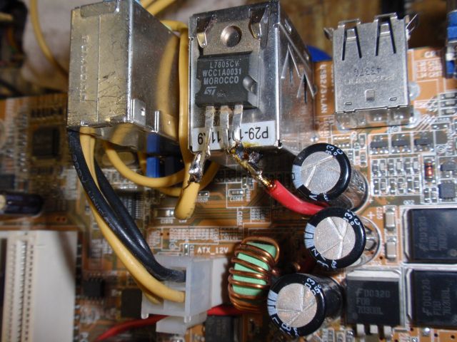
5V. 7805 circuit provides 5V voltage and can be replaced by a combination of zener diode and resistor.
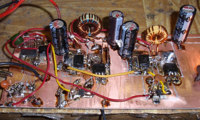
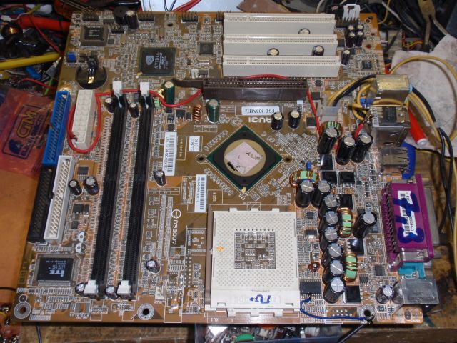
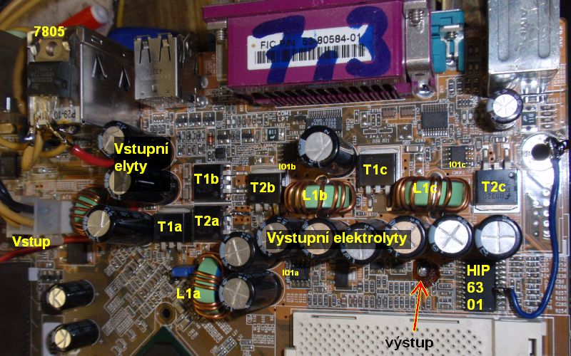
I also tried to utilize the three phase inverter directly on an botherboard.
After some modifications the inverter can be used separately. Voltage 5V for HIP6301 I obtained using 7805, so that the circuit needs 12V only.
The inverter was capable of giving a short term current of about 60A during the testing (see video below). Voltage of 1.1 V is set
connecting pin 5 to ground and disconnecting pins
1 to 4. If you want to create an adjustable inverter you must disconnect and ground the pin 10. It disables the overvoltage protection that would otherwise turn
the inverter off
at 110% of the nominal value). Thereafter, the input of error amplifier (pin 7) is fed from a voltage divider that will determine the output voltage.
Originally, there was only one resistor, leading to the output.
Lower resistor in the divider is advisable to choose 2k2 (divider current 0.5 mA). The top resistor R1 (in ohms) is calculated due to the formula:
R = (UOUT - 1.1) . 2000
Resistor also can be replaced by the potentiometer. The potentiometer should have series resistor. Operating frequency of the inverter
on this motherboard is set to
186kHz (R3 = 150k). Ripple frequency is 558kHz therefore. The output voltage should not exceed the maximum rated voltage of output of electrolytic capacitors,
which is 6.3 V. If you need a higher voltage, replace them. The output voltage is also limited by duty cycle of 75%, can therefore never
exceed 75% of the input voltage. The use of the inverter is up to you :).