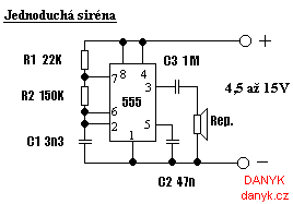
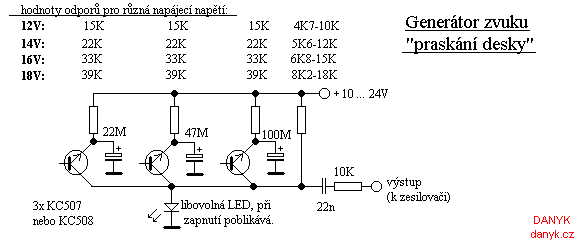
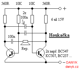
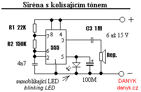
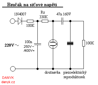
Here are schematics of several sirens and sound generators. Figure 1 shows a typical siren with 555 integrated circuit. Sound frequency is determined by R2 and C1 (the lower the value, the higher the frequency). The circuit in Figure 2 generates a characteristic cracking sound of records and can be useful for DJs. The output is mixed into the amplifier. With the component values you can experiment. Fig. 3 shows a very popular siren with two discrete transistors. Easy siren with varying tone (ambulance, police) is on Figure 4. It's similar to schematic on Figure 1, improved by self blinking LED and capacitor. LED blinking changes its own current consumption, it affects the voltage at the 5th IC pin 555 and thus the frequency. Capacitor provides a "sliding" sound, without it the siren generates two alternating tones. The speaker in the Figures 1-4 can be replaced by the piezo, it also eliminates the capacitor in series. In Figure 5 there's a buzzer powered by mains voltage. There is a piezoelectric beeper. It is interesting that the circuit does not contain any active semiconductor components. Oscillation ensures the neon lamp. Because different neon and speakers have different characteristics, it is sometimes necessary to experiment with the value of Rx.
