Introduction:
This digital thermometer with LED display allows you to measure and display the temperature in the range of -40.0 ... +150.0 °C.
The minimum and maximum measured temperature is stored and can be recalled or reset using the buttons.
The brightness of the display can also be adjusted. This thermometer is an improved version of the previous
digital thermometer with MIN / MAX. Based on this thermometr, I've also built my solar thermometer.
Construction:
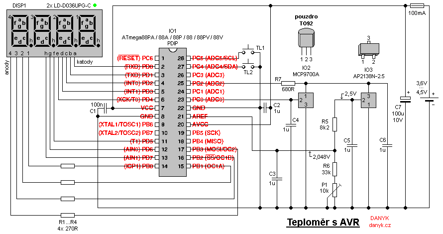
The circuit is controlled by the IO1 microcontroller - Atmel AVR ATmega88PA (or older 88P, 88A, 88, 88V or 88PV, but these might draw a littbe bit more current).
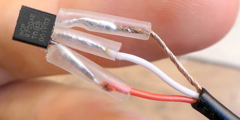
The integrated circuit IO2 type MCP9700A (or MCP9700) serves as a temperature sensor. It provides an
output voltage linearly dependent on temperature, with a coefficient of 10mV/°C + 500mV.
Thanks to the addition of the 500mV constant, it enables the measurement of negative temperatures without a negative output voltage.
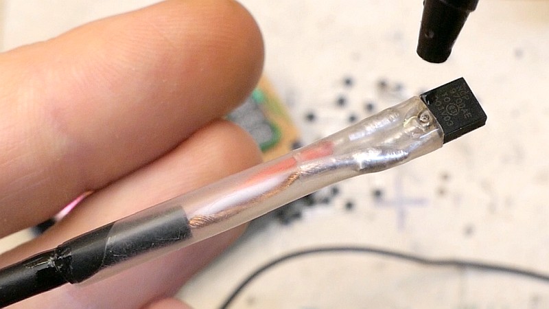
The IO2 circuit forms a temperature probe connected by a three-wire cable.
If necessary, it's in a waterproof housing.
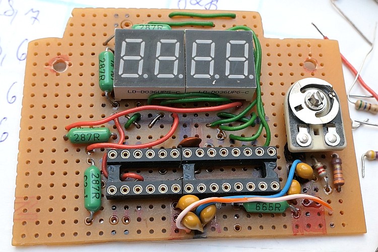
A four-digit LED display with a common anode is used to display the temperature.
The display is controlled in a multiplex. The cathodes of the display are connected to the PD port,
anodes through resistors to pins PB0 to PB3. The multiplex frequency is about 100Hz.
Resistors R1 to R4 determine the current of the display and thus its maximum brightness.
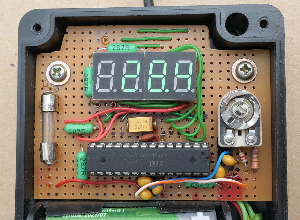
I assembled the display using a pair of two-digit LD-D036UPG-C with a very high brightness, which require a small current to achieve sufficient brightness.
It is multiplexed "the other way" - in 8 steps of 4 identical segments (first all four segments A, then all four segments B, etc.).
Thanks to this, 4 resistors are enough for the display, 8 are not needed.
The thermometer uses the input of a single ended 10-bit AD converter of ATmega88PA.
The resolution of the AD converter is increased to 11 bits using oversampling method and thus the measurement resolution is 0.1°C.
Each time the value is refreshed, 32 samples are created, these are added and the result is divided by 16. This gives a
11-bit result. For oversampling by 1 bit, 4 samples would be enough, but more samples
will bring better stability and elimination of random errors. Since the AVR's internal voltage reference is not very accurate and cannot be adjusted,
an external voltage reference IO3 is used - AP2138N-2.5, whose 2.5V output voltage enters the R5, R6, P1 divider. Using
potentiometer P1, the input voltage of the AREF pin of IO1 is set to 2.048V, which ensures a slope of 0.1°C / 1mV.
It's also possible to use AP2138N-2.1 reference (voltage regulator) that supplies 2.1V (after redesigning the voltage divider at the output).
IO1 uses a built-in RC oscillator running at 8MHz and division by 8 (CKDIV8), so it's clocked at 1MHz frequency.
A crystal is not needed - the frequency is not critical for a thermometer.
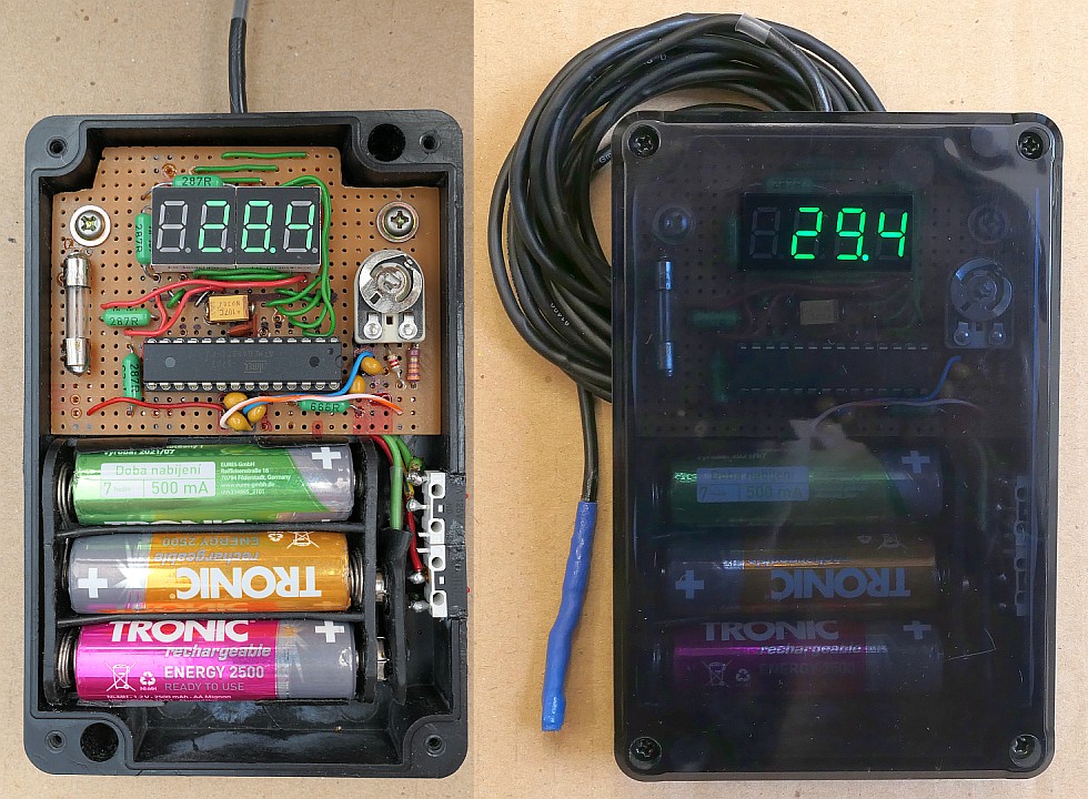
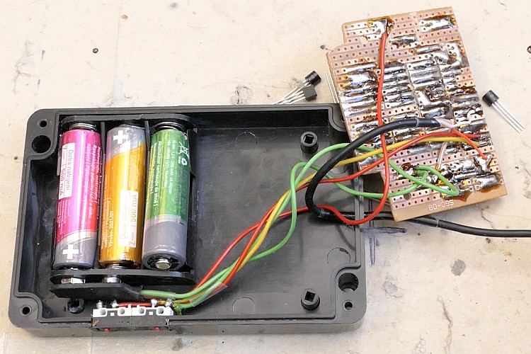
The thermometer is powered from 3 disposable AA or AAA 1.5V cells (zinc-carbon or alkaline), 3 rechargeable NiCd or NiMH 1.2V cells
or one Li-Ion or Li-Pol cell (about 3.7V).
The current consumption is roughly 0.3 - 0.5 mA at minimum brightness (about 7 months of operation with 2000mAh AA cells),
and about 3 - 5 mA at maximum brightness (almost 3 weeks of operation).
Most of the current draw is the LED display (except the lowest brightness levels), it depends on the value of R1...R4, the number of lit segments and the supply voltage.
I tested the consumption with 3.6V supply voltage and 287R as R1...R4.
Calibration:
The calibration is done by connecting a precision digital voltmeter to C3 and setting the voltage to 2.048 V using P1.
Alternatively, you can callibrate the thermometer according to a known temperature, such by immersion of a waterproof probe into
crushed ice and seting to 0.0 °C, or according to a precise thermometer.
You could also callibrate by setting P1 to show a reading according to the voltage at the output of the temperature sensor.
For example with 738mV at the output, set P1 to display 23.8 °C
(738mV - 500mV = 238mV, which for 10mV / °C means 23.8 °C).
Measurement:
The display DISP1 shows the temperature.
The refresh rate is about 1.56 Hz (refreshed every 0.64s).
Minimum / maximum function and brightness:
This thermometer monitors and stores the maximum and minimum temperature. This can be displayed by pressing
TL1 button - MIN and MAX. About 2s later, the thermometer displays the current temperature value again.
The memory of the minimum and maximum can be reset by a long press of TL1 (1s). Note: Monitoring minimum and maximum
begins after a delay of about 6-7 seconds after switching on the thermometer, in order to avoid storing corrupted values immediately after switching on, when
the circuit has'nt settled yet.
TL2 can set the brightness of the LED display in 6 steps.
Long press of TL2 (1s) turns the thermometer off. A switch in series with the battery is thus not needed.
You can turn it back on using TL1.
The AVR thermometer program for free download:
source code in assembler (ASM)
compiled HEX file (926 Bytes)
Low fuse = 62, High fuse = DF , Extended fuse = F9, Lock fuse = FF
How to write the program into the AVR is described here.