Introduction:
This solar thermometer with LED display measures and displays temperature in the range of -40.0 ... +99.9 °C and
allows you to measure, for example, the indoor or outdoor temperature.
It remembers the minimum and maximum measured value, which can be displayed or reset using a button.
The brightness of the display can also be adjusted. This thermometer is a modification of the previous one
battery powered digital thermometer.
It is powered by solar panels and stores energy in supercapacitors (ionistors).
Construction:
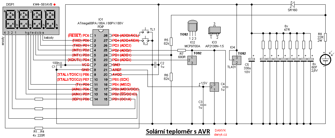
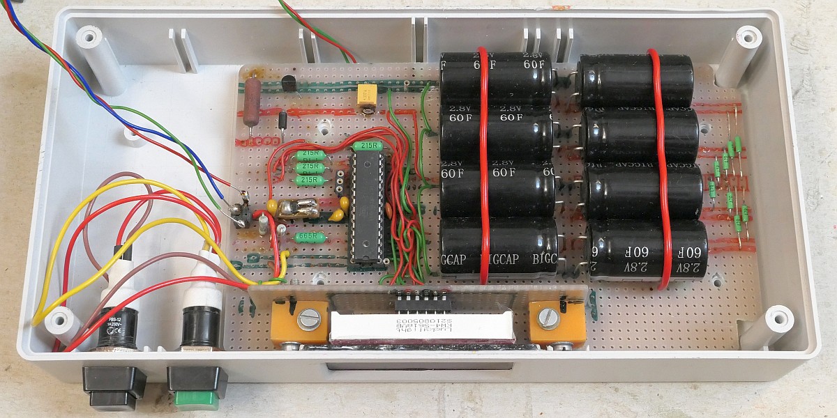
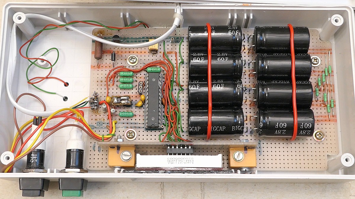
The thermometer circuit is controlled by the microcontroller IO1 - Atmel AVR ATmega88PA (or older 88A, 88V or 88PV, which may, however, have slightly higher consumption).
The integrated circuit IO2 type MCP9700A (or MCP9700) serves as a temperature sensor.
Its output voltage is linearly dependent on temperature, with a coefficient of 10mV/°C + 500mV.
Thanks to the addition of 500mV constant, it allows the measurement of negative temperatures without a negative output voltage, as is the case with the LM35.
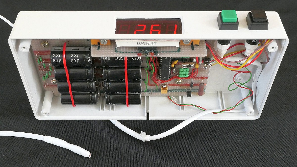
The IO2 circuit forms a temperature probe in a waterproof package connected by a three-wire cable.
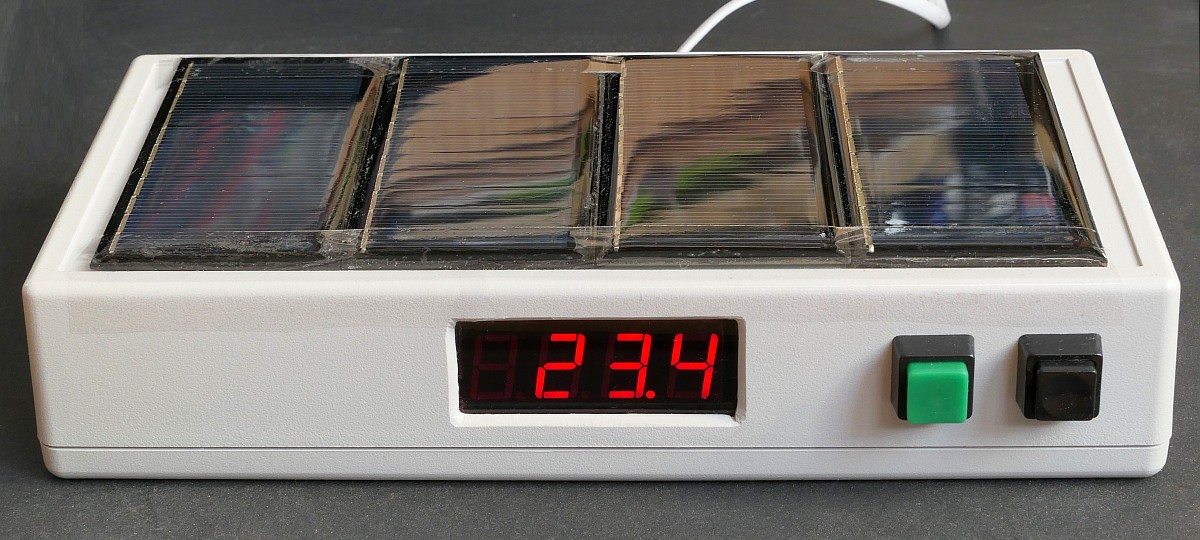
A high-brightness four-digit LED display with a common anode, e.g. KW4-561AVB, is used to display the temperature.
It's driven in multiplex at about 100Hz frequency. Display cathodes are connected to port PD, anodes through resistors to PB0 to PB3.
Resistors R1 to R4 determine the peak current of the display segments and thus the maximum brightness.
It is multiplexed "the other way" - in 8 steps of 4 identical segments (first all four segments A, then four segments B, etc.).
Thanks to this, 4 resistors are enough, 8 are not needed.
The thermometer uses the ADC0 input (pin 23) of an unbalanced 10-bit AD converter of ATmega88PA (1024 counts).
The resolution of the AD converter is increased to 1500 counts by oversampling method and thus a measurement resolution of 0.1°C is achieved.
Each time the value is refreshed, 47 samples are created, these are added, an eighth of the last sample is subtracted, and the result is divided by 32. More samples
allow better stability and elimination of random errors. Since the AVR's internal voltage reference is not very accurate,
an external voltage reference with IO3 - AP2138N-1.5 is used, whose output voltage of 1.5V enters the AREF terminal (external voltage reference input).
The Atmel IO1 uses a built-in 8MHz RC oscillator with activated predivision by eight (CKDIV8) as a clock source,
so it runs at 1MHz frequency. A crystal is not needed - the clocking frequency is not critical for a thermometer.
The thermometer works with a supply voltage of up to 2.5V limited by the TL431 reference chip,
so that the maximum voltage of the supercapacitors, typically 2.7 or 2.8 V, is not exceeded with a certain headroom.
I used a parallel combination of eight supercapacitors 60F at 2.8V (BUP002R8L606FC). Each of them has for safety reasons a
47R series resistor for current limitation in case of an internal or external short circuit.
Without it, the short-circuit current can be very high due to the low internal resistance
of supercapacitors and poses a fire hazard.
The supercapacitors are charged using solar panels. I used panels with a large enough area and a sufficient number of cells in series (10 or better 11),
so that a diffused interior light is sufficient, even when it's cloudy. There is no need for direct sunlight, the thermometer works inside the room.
The current consumption is approx. 4-5 mA at maximum brightness during the day and a supply voltage of 2.5V. The brightness can be adjusted in 5 steps.
Each step reduces the mitliplex pulse width to one half of the previous one and thus the brightness is halved. At night, the brightness is reduced to a quarter
(at the maximum brightness set at night,
the consumption is approx. 1-1.5 mA). The light level is sensed using pin 24 (ADC1 input).
Most of the current consumption is the consumption of the LED display (except for the lowest levels of brightness), it depends on the value of R1...R4,
the number of lit segments and the supply voltage.
With a supply voltage of approx. 1.9V, the display is still readable during the day. At 1.6V, the brightness is already very low and the display is readable only in the dark.
Measurement:
The display DISP1 shows the temperature in degrees Celsius with 0.1 degree resolution from -40.0 ... +99.9 °C.
The refresh rate is about 1 Hz.
Minimum / maximum function and brightness:
This thermometer monitors and stores the maximum and minimum temperature. It can be displayed by pressing the TL1 button.
With each press, the maximum and minimum are displayed alternately. About 2 seconds after releasing the button, the current temperature value is displayed again.
The minimum and maximum memory can be reset by long pressing TL1 (approx. 1s). Note: Minimum and maximum monitoring
starts after a delay of approx. 10 seconds after the meter is switched on, in order to avoid saving meaningless values immediately after switching on,
when the thermometer circuit has not yet stabilized. Using TL2, the brightness of the LED display can be adjusted in 5 steps
(a subsequent press of TL1 or a long press of TL2 will save the brightness setting to EEPROM so that it can be restored after power loss).
The thermometer can be turned off by long pressing TL2 (1s), then switched on by pressing TL1.
The AVR thermometer program for free download:
source code in assembler (ASM)
compiled HEX file (1114 Bytes)
Low fuse = 62, High fuse = DF , Extended fuse = F9, Lock fuse = FF
How to write the program into the AVR is described here.